Scene: road accidents
Scene is the geosit package for the survey of road accidents. In a scene you measure the impact point, the debris, the skid marks, the road edges and the vehicles; at the end geosit prepares the site sketch in PDF, to attach to the report, and the layered DXF for the technician.
The Scene package is needed
Scene is added on top of basic geosit: the license says which packages there are (Settings → License, Packages row). During the trial days there is everything. Without the package the «Scene» choice does not appear; a scene already made always opens and can always be exported, but it cannot be measured.
Opening a scene
Project → + → Scene.
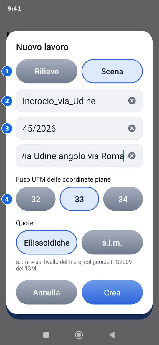
- Survey or Scene: a normal project or a scene.
- The name: geosit suggests
Scene_with date and time; you can change it. - Report number and location (street, kilometre, junction): they go at the top of the sketch.
- Reference system and elevations, as for any project (see Creating a project).
Report and location can be corrected later too: press and hold the scene in the list of projects → Report and location.
Every new scene already has the Photo attribute: after each measured element (impact, debris…) the point card opens with Shoot and Gallery. After the wheels of the vehicles and the vertices of the lines the card does not open. Other attributes (for example Notes) are added as in any project: see Point attributes.
The palette
In the survey of a scene, above the name and the code of the point there is a row of choices that scrolls with your finger: it says what you are measuring now.
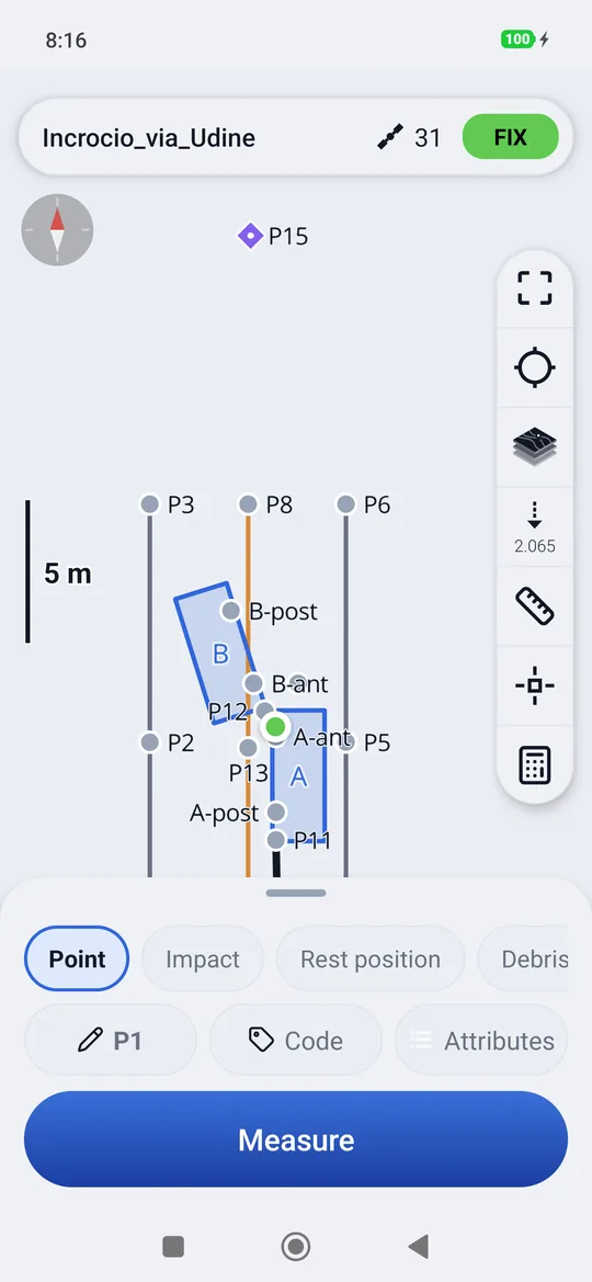
| Choice | What it does |
|---|---|
| Point | Any point, with the code written by hand |
| Impact, Rest position, Debris, Person, Sign | A point with that code: the impact point, the rest position, the debris, a person, a road sign |
| Skid mark, Road edge, Lane marking | A line: each measurement adds a vertex. Tapping the same choice again starts a new line (the second skid mark, the other road edge) |
| Vehicle | A vehicle from two measurements, see below |
Above the palette a row reminds you where you are, for example Skid mark · 3 points · tap «Skid mark» again for a new one.
The vehicles
A vehicle is surveyed with two points: the centre of the front wheel and that of the rear wheel on the same side. The vehicle dimensions do the rest.
- Tap Vehicle: the button becomes Measure the front wheel. Put the pole on the centre of the front wheel and measure.
- The button becomes Measure the rear wheel: the same on the rear one, on the same side.
- The vehicle window opens.
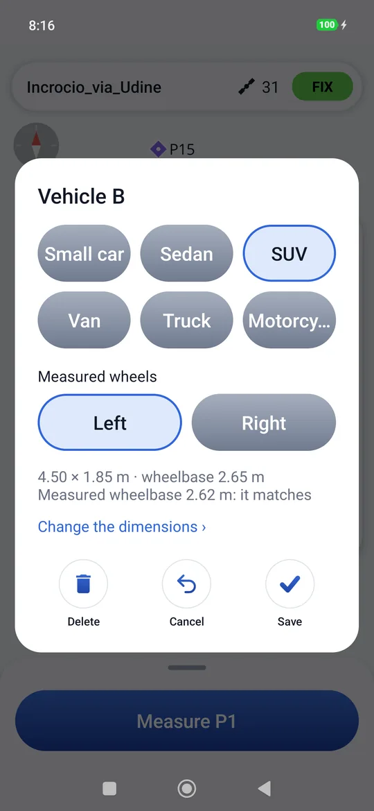
- The category: small car, sedan, SUV, van, truck, motorcycle. Each has typical length, width, wheelbase, overhang and track.
- Measured wheels: Left or Right, as seen by whoever drives the vehicle. It decides on which side of the wheels the body lies.
- The wheelbase check: the distance measured between the two wheels is compared with the wheelbase of the category. If it matches (within 15 cm) it is fine; if it does not match, check that you took the right wheels or change category.
- Change the dimensions: the five dimensions written by hand, for example from the registration certificate.
Save draws the outline to scale on the map, with the letter of the vehicle (A, B, C…). No vehicle leaves the two wheel points without an outline. The wheel points are named after the vehicle (A-ant, A-post) and do not use up the point numbering.
Tapping the outline on the map reopens the vehicle window: you change category, side or dimensions and save, or you delete the vehicle. Once the vehicle is deleted, the two wheel points remain in the project.
The measured wheelbase is the real one
The outline rests on the two measured wheels: the front and rear overhang and the width come from the category, the position and the direction from the wheels. If you delete one of the two wheel points, the vehicle goes away with it.
Sketch and DXF
Project → press and hold the project → Export: in a scene the first two items are for it.
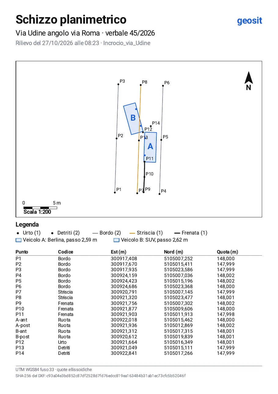
- Site sketch PDF: an A4 sheet with location, report, date and time of the survey; the drawing at a round scale (1:100, 1:200, 1:250…) with the north arrow and the scale bar; the legend (how many elements of each type, the lines, the vehicles with category and measured wheelbase); the table of points with the grid coordinates and the elevation; at the bottom the SHA-256 fingerprint of the DXF.
- Layered DXF: each element in its own layer (URTO, DETRITI…, RUOTE, PUNTI), the names in NOMI, skid marks, road edges and lane markings as polylines (FRENATE, BORDI, STRISCE), the vehicles as closed outlines with the name (VEICOLI). Grid coordinates in the scene's reference system.
What the fingerprint is for
The fingerprint printed on the sketch is that of the DXF exported with it. Whoever receives the two files
can recompute it on the DXF (for example with sha256sum): if it is the same, the DXF is exactly the one
drawn in the sketch, without changes.
CSV, KML and raw data files remain as in any project: see Import and export.