Pro: CAD drawings and snap
With the Pro package you load a DXF drawing into the project (the design, the survey of the existing state, the map extract) and you see it on the map with its lines, its colors and its texts. With the snap crosshair you pick a precise point of the drawing (vertex, endpoint, midpoint, center, intersection…), you create it as a point of the project and you stake it out.
The Pro package is needed
The Pro package is added on top of the basic geosit: the license says which packages are included (Settings → License, Packages row). During the trial days everything is included. Without the package the drawings already loaded stay on the map, but no new ones can be loaded and the crosshair is not there.
Loading a drawing
Project → press and hold the project → Import → choose the .dxf file. The drawing goes into that project.
geosit reads text DXF files of all versions, from the old R12 to the most recent ones, even tens of megabytes in size: lines, polylines (also with arcs), arcs, circles, ellipses, curves, points, texts and attributes, the boundaries of hatches and the blocks, even nested, rotated, scaled or mirrored. Left out are the hatch fill, images and paper space.
Which coordinates the drawing is in
The drawing must be georeferenced: in real coordinates, not around the origin. geosit recognizes the system by itself, in this order:
- the system written in the file, if the CAD put it there;
- the zone written in the name of the file (for example
planimetria_UTM33N.dxf); - the numbers of the coordinates.
| Coordinates | What geosit does |
|---|---|
| UTM (WGS84, ETRF2000, RDN2008) with known zone | Loads the drawing and brings it into the project's system |
| UTM without zone | Asks for the zone (see below) |
| Latitude and longitude in degrees | Loads the drawing and brings it into the project's system |
| Gauss-Boaga (Roma40), ED50 or another EPSG system | Transforms it and brings it into the project's system; if the phone does not have all the systems yet, it asks to download them (see Reference system) |
| Local coordinates | Keeps it aside, in limbo, and opens the georeferencing right away |
From the numbers the UTM zone cannot be worked out: the same coordinates are a valid point in zone 32 as in zone 33, five hundred kilometers apart. If the file does not say, geosit asks which zone it is in, and under each zone it writes how far the drawing would end up from you (or from the project's points): the right one is close.
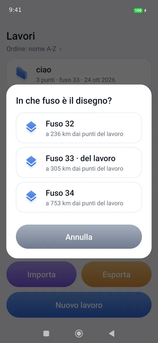
At the end a message says how many lines, points, texts and layers have arrived. If the file contains objects far from the real drawing (a title block or sections drawn around the origin), geosit leaves them out and says so.
DWG, binary DXF, external references
.dwg files cannot be read: from the CAD save the drawing as DXF, preferably as text (ASCII). If the drawing is made of external references (xrefs), in the CAD they must first be bound to the drawing, otherwise the DXF stays empty.
The drawing on the map
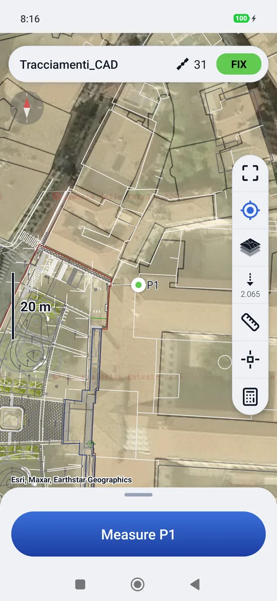
In the survey and in the stakeout the drawing lies above the map and below the points, with the CAD colors; the CAD white and black follow the theme (dark by day, light by night). The texts have their real height: they grow when you get closer, as in a CAD, and appear when they are large enough to read. Zoom to fit includes the drawings too.
The snap crosshair
In the column on the right of the map there is the snap command (the small square with the cross): it appears when the project has a drawing. When you tap it, the crosshair, a thin cross, appears in the center of the map, and the snap bar at the bottom.
The crosshair stays still: you drag the map, so your finger never covers what you are looking for. Around the crosshair you see the snappable points, each with its own mark: a small square on vertices and line ends, a small triangle on midpoints, a small X on intersections, a small circle on centers, a diamond on nodes. So you see where you are going before you get there.
When a point is close enough, the crosshair snaps to it by itself, like a magnet: the mark lights up in orange and a dashed line joins it to the center of the crosshair. You do not need to center it. A tap on the map brings under the crosshair the snappable point closest to your finger, or the place you tapped if there is nothing there.
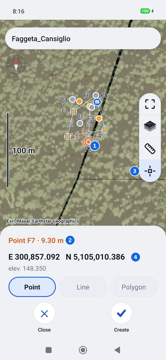
- The crosshair: the center of the cross is where it searches; the orange mark, joined by the dashes, is the snapped point.
- What has been snapped and how far from the crosshair: a project point (Point P4 · 0.42 m, which wins over the drawing), or the mode and layer of the drawing, for example Vertex · 0.42 m · 00_LO_pietra. If there is nothing around the crosshair: Free point, that is the exact place under the crosshair.
- Snap, held down, opens the Layers: what to snap to, which layers to see and the georeferencing, see below.
- The grid coordinates of the point, always in full, and its elevation, if there is one; with the receiver connected also how far from you.
- Create, Stake out and Close.
| Mode | Snaps to |
|---|---|
| Endpoint | The two ends of a line or of an open polyline |
| Vertex | Every vertex of lines and polylines |
| Midpoint | The middle of every segment between two vertices, also along an arc |
| Center | The center of circles, arcs and ellipses |
| Node | The CAD points and the insertion point of symbols (blocks) |
| Intersection | Where two lines cross |
| Perpendicular | The foot of the perpendicular from your position to the line (the receiver must be connected) |
| On line | The point of the line closest to the crosshair, when there is nothing else around |
The modes are turned on and off in Layers, under Snap to, and geosit remembers them. By default the first six are on. The snap searches within a generous finger's width of the crosshair, and among several points it chooses the closest one.
Creating and staking out a point
- Create opens the New point dialog already filled in: the next name, latitude and longitude of the snapped point and its elevation, if the drawing has it (read in the project's elevation system). Everything can be changed; Insert saves it in the project, like a point entered manually.
- Stake out opens the stakeout on the snapped spot without saving a point: the target is called «CAD». If you are already in the stakeout, it becomes the new target. If you want to keep it, Measure here measures it and saves it.
- Close (or the back button) leaves the crosshair.
A 2D drawing has no elevations
Many drawings are flat: everything at elevation zero. There geosit writes no elevation and the created point has no elevation, instead of inventing a zero.
Layers and drawings
Holding down the snap opens the Layers: Snap to at the top, with the snap modes to tick, and below it the list of the project's drawings with their layers, in alphabetical order. Layers that are off are not shown and cannot be snapped to; All and None turn them on or off together. At the start the ones that are on in the CAD are on.
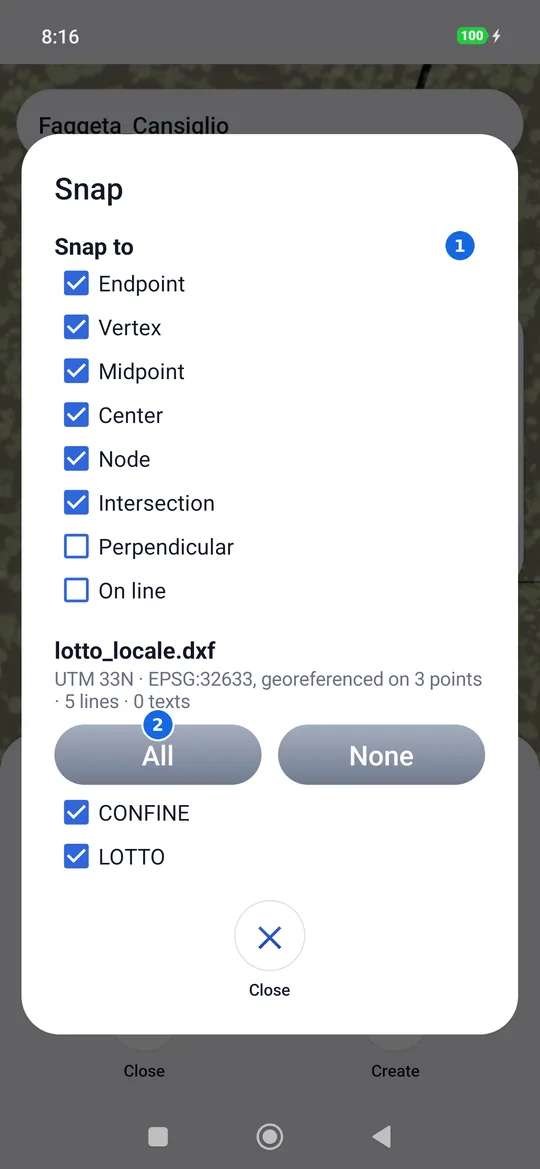
- Snap to: the snap modes, the tick turns them on or off.
- All or None of the drawing's layers; below, each layer with its tick.
At the bottom of each drawing's list, Delete this drawing removes it from the project; the created points stay. A project can have several drawings, and they are deleted together with the project.
Georeferencing a drawing
A drawing in local coordinates (a survey with its origin at an arbitrary point, a design plan) does not know where it is. geosit warns you and keeps it aside, in limbo: it is not on the map or in snapping until you georeference it, and the georeferencing opens by itself. The same command is in Layers, under each drawing: it also fixes a drawing that is already georeferenced but slightly shifted. It also opens from the Calculations, at the bottom of the list, when the project has drawings.
You work in pairs, with the snap crosshair: you drag the map, the crosshair stays still.
- Aim at a point of the drawing (a vertex, an endpoint: the crosshair snaps) and tap Take. A drawing in local coordinates is shown in limbo: alone, without background or points, with its own X and Y under the crosshair. After Take you move to the real map by yourself, framed on the project's points.
- Aim at where that point really is: a project point (the crosshair snaps to the nearest) or a point on the map. Tap Goes here: the pair is done and the Pairs table opens, full screen. With the receiver connected there is also Measure here: stand with the pole on that point and tap it; geosit measures it as in the survey (FIX, average over the set seconds), saves it in the project and closes the pair. While it measures, the same command cancels.
- Add takes you back to the drawing for the next pair (in limbo, while there is only one pair). From two pairs the drawing moves into place on the real map and you aim at it there; from the third each pair has its residual.
- In the table tap Apply.
On the map, Pairs opens the table again, even halfway through a pair; the back button does the same.
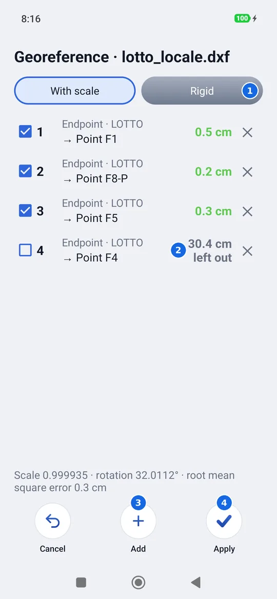
- With scale or Rigid, see below.
- A pair: the point of the drawing, where it goes and its residual. The check mark keeps it or leaves it out, the cross removes it.
- Add goes back to the map for another pair.
- Apply saves the drawing in its place.
| Mode | What it computes | When |
|---|---|---|
| With scale | Shift, rotation and a scale factor | The normal case: the drawing may be slightly off scale or in another unit. |
| Rigid | Only shift and rotation, scale 1 | The drawing is already in true metres and its scale must not change. |
The residual of a pair is how far the point of the drawing falls from its true point after the computation: green up to 5 cm, orange up to 25 cm, red beyond. A pair with a residual much larger than the others is usually a badly taken point, or one that is wrong in the drawing: clear its check mark and the computation is redone without it, while its residual stays visible. Below the table are the scale, the rotation and the root mean square error of the pairs kept. The drawing moves only in plan: its elevations stay its own.
Two pairs are enough, three are better
With two pairs the drawing goes into place, but nothing checks it: the residuals are necessarily zero. The third pair tells whether the others are good. Choose points far apart, at the edges of the drawing.
The georeferencing stays with the drawing, even when you leave the project, and geosit keeps its pairs. Reopening Georeference brings the table back as it was: you can add pairs, switch them off or remove them, then Apply recomputes always starting from the original drawing, so corrections do not add up. Layers shows Remove the georeferencing: the drawing goes back to how it was when imported and the pairs are deleted. Cancel, or the back button from the table, leaves the georeferencing without touching the drawing; if you changed something, geosit asks first.